Dimensioning Sheet Metal Flat Pattern

New To Sheet Metal Looking For Feedback About Dimensioning Autodesk Community Inventor

New To Sheet Metal Looking For Feedback About Dimensioning Autodesk Community Inventor

Sheet Metal Layout Tip Dimension To Formed View Not Flat Pattern

Sheet Metal Layout Tip Dimension To Formed View Not Flat Pattern

How To Define The Mbd Data Of Sheet Metal Parts Engineers Rule

How To Define The Mbd Data Of Sheet Metal Parts Engineers Rule

What Happened To My Flat Pattern View Computer Aided Technology

What Happened To My Flat Pattern View Computer Aided Technology

Solved Sheet Metal Drawings Dimension Problem Autodesk Community Inventor

Solved Sheet Metal Drawings Dimension Problem Autodesk Community Inventor

Drawing The Inventor Flat Pattern

Drawing The Inventor Flat Pattern

Drawing The Inventor Flat Pattern

Calculate the value bend allowance for required sheet metal bend by using below formula.

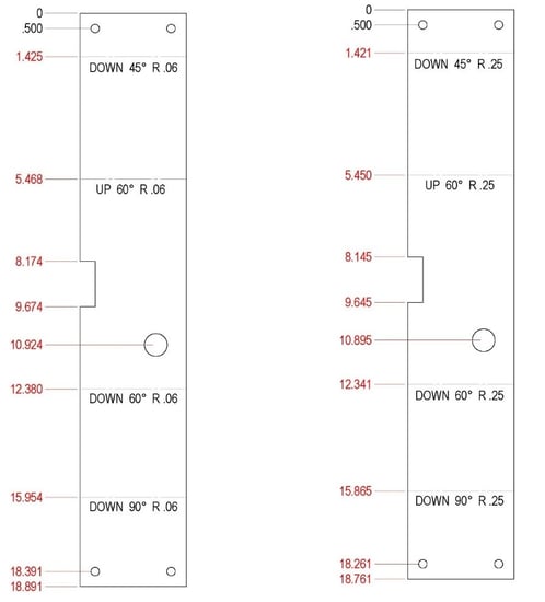
Dimensioning sheet metal flat pattern.

Sheet metal flat length can be calculated in the following three simple steps. The flat pattern drawing doesn t always list these factors. Oml outside mold line the intersection of two outside surfaces of a part extended past the bend. Flat patterns of all bodies appear at the end of the featuremanager design tree.

When you expand the representation of a body in the cut list the body s flat pattern appears at the end of its feature list. Lets go ahead and include all the fastener locations. Flat pattern terminology iml oml c l radius flat pattern the outline definition of the part in it s flat state before forming. When producing drawings of sheet metal components i dimension from inside the flange walls.

I think this is the better way because you can acquire your cutting length without a flat pattern by adding the inside lengths fold allowance. Dimensions given on a flat pattern are affected by several bending factors like k factor and bend radius during the 3d modeling stage. Enter flange length internal radius and thickness values. Keep default values in calculator as zero.

My boss dimensions from outside the flange walls and thinks. Enter k factor values. Value of bend deduction and flat pattern are shown in result section. Multibody sheet metal parts.

The flat pattern drawing doesn t always list these factors. And also find you fold centers more easily. Bend allowance ba π 180 r k t a. Generally capabilities of of 0 9mm 20mm in thickness are able to be manufactured from sheet 3mm or plate 3mm but this tolerance depends mainly on the part.

If the value of sheet metal k factor and bending flange length is known. When considering sheet metal thickness a single sheet with punches holes is a good rule of thumb. The sketch and locating dimensions are retained.

R11 Flat Pattern Vs Iv2008 Flat Pattern Autodesk Community Inventor

R11 Flat Pattern Vs Iv2008 Flat Pattern Autodesk Community Inventor

Solved Flat Pattern Dimensions In Parts List Again Autodesk Community Inventor

Solved Flat Pattern Dimensions In Parts List Again Autodesk Community Inventor

Standard For Dimensioning Sheet Metal Flat Patterns Induced Info

Standard For Dimensioning Sheet Metal Flat Patterns Induced Info

3d Cad Modeling Of Sheet Metal Parts

3d Cad Modeling Of Sheet Metal Parts

Source : pinterest.com